RC Boat Rudder Design Notes
Want plans for this project? Get them at the Plan Store.
RC boat rudder made simple – learn how to figure out type, size, linkage, placement of the rudder and how to tune your radio controlled boat for best steering response.
An RC boat rudder that is scaled down from the original plan of a full-size vessel will almost without exception have an impaired steering response, and never handle as well as the original vessel.
|
The reason is quite simple: The physics behind rudder size doesn't change linearly with scale. It comes down to this: a scaled down boat, all else being equal, need a bigger rudder area than the original vessel. Increasing the rudder area is the most direct way to solve the issue.However, area is not the only property that effect steering performance and scale appearance. Some of the other propertied include: shape, amount of balance, location, rake and shape of horizontal section. So there are several means to improve or effect the boat's behavior that I'll try and address as well.
This said, when building a radio controlled scale model we have two considerations:
- Make it look scale-like out of water but compromise performance and appearance
- Sacrifice scale accuracy for the benefit of a more scale-like on-the-water appearance
Most builders may not be aware that there is an issue and will go down the path of #1 above without knowing any better. At the same time, since the main purpose of a radio controlled boat is not being a conversation piece for your living room, the majority of builders would rather have good performance on the water and choose #2.
For the rest of this page, I'm assuming performance trumps scale appearance as it otherwise applies to static scale models. So here we go.
RC boat rudder design
|
There is no set formula that determines what size to make your RC boat rudder. Some books I've read have suggested some rules of thumb to determine rudder size. Vic Smeed in "Boat Modelling" for instance suggest to use 1 1/4 square inches of rudder area for every foot your boat is long.
Other sources (I can't remember where exactly) in conjunction with RC sailboats, suggested the rudder should be 10% of the total lateral plane (underwater profile of hull+rudder). I can't vouch for either of these "rules", but it may provide you with a place to start your own trial & error.
If you have a model, whose response you're happy with, use its rudder arrangement as a guide for your new efforts. There is little sense in reinventing the wheel.
The area of your RC boat rudder may be the most important factor effecting the steering performance of your radio controlled boat, but as I've hinted to earlier, there are other factors as well. Some of those are listed below, in no particular order.
Hull Proportions
The hull proportions have a big impact. Problematic ships are often long with either high displacement or narrow beam. Examples include warships such as destroyers, battleships, and civilian and merchant ships such as oil tankers, merchant ships, liberty ships, barges etc. Favorable proportions are common amongst launches, tug boats and pleasure boats.
Speed
Higher speed helps improve steering performance with otherwise similar hull and rudder. Obviously, your boat will still have issues when navigating at lower speed and when docking etc.
Rudder Proportions and Location
A rudder is more effective when placed directly in the prop wash. Some ships around the turn-of-the-century actually had the propeller behind the rudder – no joke. Those were mostly torpedo boats some of which were in the British, French, Russian and US navies.
To mimic this on a radio controlled boat is sure to disappoint in terms of performance, so avoid the vessel all together or side-step the design with a more traditional layout where the rudder is behind the propeller.
Single vs. Multiple Propellers and Rudders
Suppose we have two almost identical vessels – one with a single propeller and rudder, the other a dual set-up. I don't think you can automatically conclude that one will control better than the other. However, with dual propellers there is an opportunity to implement an independent motor control scheme for the left and right hand propellers. This type of arrangement will significantly improve slow speed control performance.
Ballasting
Another thing that is often overlooked, is where ballast is placed along the length of a hull. Most of us place the model in the bathtub and lay weights on or in the hull until it is trimmed to design waterline. This is all fine and good but most of us don't realize that weights placed at the extremes will give the hull a higher inertia (in the yaw axis in airplane terms) than one where the ballast is placed centrally. The higher inertia boat will be more difficult to maneuver. Having said that, that is not the whole story though. If over done, a vessel where the ends are too light will look out-of-scale when encountering rougher water and appear more cork-like.
Angular Movement
Some builders seem to believe that by having the rudder angle increased will compensate for a small rudder area. This is not true. An excessive angle will make the RC boat appear tippy and unstable when in tight turns. Typically it is best to stay close to the full-scale vessel, which in most cases is +/- 25 to 30 degrees, but not to exceed +/- 35 degrees.
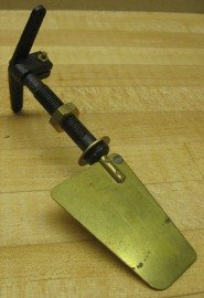
Balanced vs. Non-Balanced Rudder
A non-balanced rudder has the axis-of-rotation at the leading-edge of the rudder. A balanced rudder has approximately 20% or less of its total area in front of the axis-of-rotation. A balanced rudder has several advantages in powered boats:
A larger percentage of the prop wash is diverted which leads to a stronger thrust side component when the helm is hard to one side.
The holding force required to maintain an angle on the rudder is reduced, so your servo doesn't need to work as hard.
Sometimes it looks awkward growing a rudder further towards the stern when you're trying to add some area to it. Letting it grow forward may be less obvious and look better.
In the old classic "Elements of Yacht Design" by Norman L. Skene, the author discourages the use of a balanced rudder on sailing yachts. When sailing and the boat is heeling, it is common that the rudder needs a substantial trim to one side just to sail straight (called "weather helm"). His reasoning is that, having a balanced rudder means the front piece of the same is disturbing the fairing of the hull-rudder transition on the opposite side of the hull. This leads to unnecessary turbulence and drag which inhibit speed.
Shape of the Rudder
Some rudders are deep and narrow, while others are wide and shallow. Which work better? My vote goes to deep and narrow, here is why:
Balanced or not, being narrower will place the center of pressure on the rudder closer to its axis than a wide rudder. This will take strain off your steering servo.
A deeper rudder will also have the center of pressure lower down. If it is sufficiently deep down (and below the “center of lateral resistance”), the effect will be a significantly reduced tendency to heel when the helm is hard over, especially on shallow and narrow hulls.
A downside to a cantilevered narrow and deep rudder is more strain on the rudder stock. This, in my opinion, is a minor issue and not something I've ever really considered given the vast benefits.
The cross section (As cut parallel to the design water line) has varied through history. The most advantageous shape is to make the rudder as thin as possible in general, but in particularly at the trailing edge.
If the rudder is free standing (not integrated in a keel or skeg), the most efficient shape is that of an aerofoil. If the rudder is integrated into a keel such as were the case in sailing yachts from the first half of the twentieth century, the rudder is best faired into the keel with the rudder stock being a round rod at the leading edge.
Sometimes you see raking rudders on sailing yachts and some historic ships. The rake angle has two purposes: It helps optimize the shape of the lateral plane and help neutralize the lifting component that a rudder with vertical post has when the yacht or ship is heeled.
RC boat rudders for high performance speed boats is a world all by itself that I know very little about. If that is where your interest lies, there are other really good resources for information on the web.
Rudder Linkage
|
For high performance sailing yachts and power boats, I'd recommend using ball links in all link joints. Ball links are commonly used by the RC airplane and helicopter community and also in RC car and buggy. They are back lash free and give superior control in critical applications.
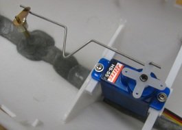
For modest performing scale boats and casual RC boats in general, a bent up piece of piano wire will do the job just fine. I say piano wire, but that's not what I use. I use 17-4 PH stainless steel wire.
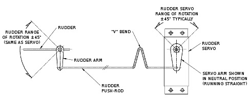
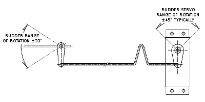
Below are a couple of illustrations showing a typical RC boat rudder linkage. It is best to make sure the servo arm and rudder arm are parallel at neutral position.
Also note the "V" bend - its a great feature allowing you to bend the linkage outside the assembly and tweak the length by adjusting the angles of the "V" once its all mounted in the model. Believe me, this also saves wire.
|
The first illustration shows an RC boat rudder sweep angle of +/-45 degrees. This is the most convenient, since the arms on the rudder and servo are the same length.
It is also the "correct" way to make a servo linkage as the rod will stay parallel with a common center-line through the two pivot points. As a result, the rudder angle is split exactly down the middle (+/-45 degrees).
The problem with having the arms the same length is that, as described earlier, the rudder should be limited to less than +/-35 degrees for best performance. The way this is accomplished is illustrated below.
|
A minor issue with this RC boat rudder arrangement is that the stroke of the rudder no longer is symmetrical - it's geometrically impossible with this design. However, the difference between the left and right stroke is less than one degree, so in all practical aspects it will work just fine.


