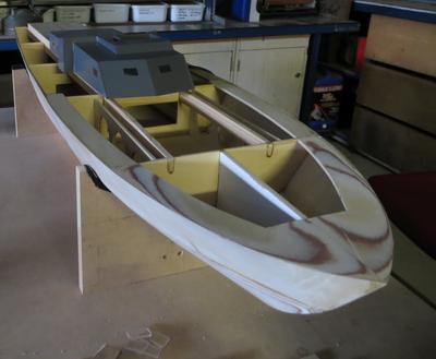
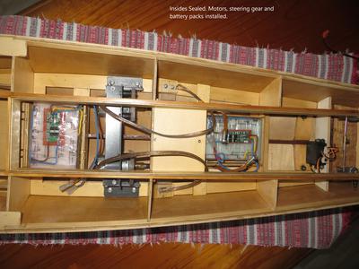
ELCO PT-109
by Stephen Somogyi
(Barrington NSW Australia)
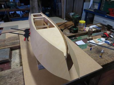
Sheeting with .8mm ply
Hi All.
My model is based on Petter Blix's 1:24 scale plans and instructions downloaded and printed to full size.
As my main hobby is electronics I was aiming to build a fairly lifelike model as a platform for RC control of propulsion, steering, lighting, armament triggering, radar motion and anything else I could think of and fabricate.
Petter's plan allows relatively quick construction with plenty of room for machinery and control circuitry to be housed within the hull and on the deck.
So far I have spent about twelve months on the project but I have also spent time learning fine wood working techniques, metal turning skills on a small lathe for various brass shafts and bushes, fibre-glassing the hull with tissue and polyester resin and RC control of DC motors, Stepper motors and switches.
I also converted my son's RC racing boat into a rescue tender which would tow the PT Boat back to shore in case it ran out of fuel, i.e. the batteries went flat.
The frame is of 3mm 3ply.
Hull is sheeted using 0.8mm 3ply reinforced with fibreglass tissue and polyester resin and polyester finish cote.
Sealed internally with clear estapol.
I made the deck housing from 3mm clear plastic as I thought it would be easier to make windows by masking and spray painting the surrounds. (I want the cabin lights to be seen when the crew are resting and reading letters from home).
The deck lining has been left till all the internal fit-out is complete to allow easier access.
Carried out a Float Test in neighbor's pool. YAY IT FLOATS !!!
A little high which allows more equipment to be fitted.
If anyone is interested, I can provide more detail on any aspect of what I have done so far.
Good night everyone,
Stephen
Rudder detail added 7/13/2021
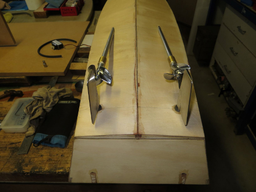
I was worried that with the boat weighing around 4kg the rudders and steering gear could be easily damaged if the boat ran aground. This was highly likely while the Skipper was in training, so I decided to fabricate the rudders, shafts and tubes out of stainless steel. Luckily I have the facilities to carry out this work, although not at this scale.
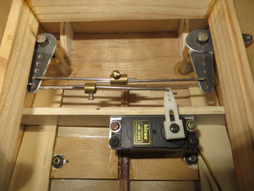
Attached pics show some steps taken to achieve the shape according to Petter’s drawings.
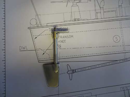 |
The rudder plate is of 3mm s/s section cut from some angle off-cuts, the shaft is 6mm s/s round bar salvaged from an old printer and the tube is 3/8” (10mm) OD s/s pipe. The plastic bearing tubing is electrical insulating spaghetti from a big old office printer. So much to salvage from those old machines and so many sent to the tip.
The adjustable connectors (shaft to servo) are from 1mm s/s welding filler rod, and the brass adjusters are cable connectors from old electrical switch fittings.
In place of bearings, I used plastic tubing between the shaft and tube. The brass header is sealed to the tube and shaft with neoprene “o” rings.
I found the hardest part was drilling the holes through the hull. The Shafts had to be perpendicular to the DWL longitudinally and parallel to the vertical axis laterally.
I ended up securing the hull on it’s side with the beam vertical (over my work bench), then gluing a small spirit level to the surface of my drill which was parallel to the drill bit. This gave me the correct lateral angle.
I then recorded the angle between the shaft and keel from the drawings and marked this on the work bench surface, giving me the correct longitudinal angle. Then, while viewing the drill from above I was able to keep the drill horizontal and in line with the 90deg marker.
A trained ship builder might detect a small alignment discrepancy but I was tickled pink (overjoyed) with the result.
While doing the float test, I gave the boat a gentle push across the pool and was pleased to see she crossed the pool in a straight line, no deviation at all.
 |
 |
