Simple RC Boat Hull
Want plans for this project? Get them at the Plan Store.
Follow this RC boat hull building tutorial for an easy and inexpensive balsa model boat. This is part two where the hull frame is finished and getting ready for planking.
In preparing the RC boat hull for the next step, you can now carefully remove the structure from the building board. Don't worry if the wax paper sticks to the hull or rips. Even if the wax paper looks clean and comes right off, I'd opt to replace it for the next step. A spilled drop of glue or other debris can mess you up, so better safe than sorry.
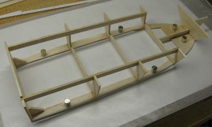 This is where we left off after the previous build log.
Also, at this point the hull alignment template, that was placed under the wax paper to guide component placement and alignment, has served its purpose. Now is a good time to separate the hull structure from the wax paper for a closer inspection.
Typically, if any CA glue got between the balsa and wax paper, the wax paper will rip. That's part for the course. Carefully peel it off the balsa. Go easy as the hull structure is fairly delicate at this stage.
At this point I turned the alignment template under the wax paper upside down and placed a fresh piece of wax paper on top. It provides a better background than my ugly build board. The light background provides good contrast and makes it easier to spot things that are out of the norm or dropped items or spilled glue.
The Deck
Give the deck side of the structure a light sanding with 120 grit sandpaper backed with a flat sanding block. Go easy as the only purpose is to take down any obvious high spots.
Put the hull frame aside while we focus on the two deck halves (item "B" on the plans). Align them at the pinnacle of the stem and check alignment at the rear edge where they join. At this point, place a piece of office or thin packing tape over the joint to temporarily hold them together. Place the deck on the building board with the tape facing down. Lift the assembly off the board carefully near the tape, just enough for the joint to open up and place some CA glue before placing the deck back on the board. Hold it down flat while the glue cures.
Pin or weigh the deck down on the building board.
Mark the bulkhead locations across the same way as you did on the chine shelf. The lines will be a visual aid when aligning the deck to the hull.
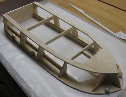 RC boat hull with deck facing down.
Place the hull frame on top and position the raised part of the transom inbetween the "legs" of the deck. When aligning the frame to the deck, the stem is the most important, both in being centered and alignment front to back.
Keep in mind that it is the top of the deck that after sanding should line up with the profile angle of the stem piece, so looking at it all as assembled, the frame will sit back a couple of millimeters from the foremost point on the deck.
As the stem is lined up, glance at the bulkhead locations as marked on the deck. Don't expect them all to line up perfectly, but it will give you a good idea of how close to ideal you are at this point.
Also check and make sure the frame is making contact with the deck along the deck stringers, transom, bulkheads and the stem piece. If care has been taken so far in cutting out the parts and aligning, nothing should be too far out of alignment.
When things look good place drops of thin CA along stem piece, bulkheads and deck stringers.
Prepping the Keel
Many builders would go ahead and attach the keel at this point without a second's thought. However, when it comes to installing a propeller shaft most of those builders would be scratching their heads trying to get a propeller shaft tunnel aligned correctly. It would require a jig, extra long drill and some luck to get it right.
We're going to take much of the tool requirements out of it and stop relying on luck for success, here is how.
 Keel cut to shape and two pieces of basswood or hard balsa for the propeller shaft tunnel.
To do this you need two pieces of basswood or hard balsa approximately 1/8 X 5/16 X 2 inches (3 X 8 X 50mm) that will act as doublers on either side of the keel. Do as follows:
On the keel, we need to stay clear of the bulkhead #4 location, so make sure the keel is well marked in that area. Next, lay the keel (template down) on a flat surface and glue one doubler to the back side of the keel just ahead of the #4 bulkhead location and line it up parallell with the bottom of the keel.
If you're off by a few millimeters from either that's fine. Try not to have the doubler extend passed the bottom of the keel, it's better if you err on the other side.
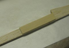 First doubler glued to the back of the keel.
Next flip the keel over and trim away the area between the two phantom-lines. This can be done with a razor blade and a straight edge or with a razor saw. Try hard not to cut into the doubler.
The prototype used a 4mm outer diameter stuffing tube, so that's the size marked on the drawing and template. Since the keel is made from 1/8" (3.2mm) thick material the tunnel you cut will be too tight from side to side. This can be fixed later with a long 4mm drill or a needle file and some elbow grease.
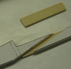 Trim away the area of the keel where the propeller will pass through it, thus creating a tunnel for ditto.
Now peel away the template (make sure all bulkhead locations are transferred first!) and place it on a flat surface with the attached doubler facing down. Prop up either extreme of the keel with scraps of material until level and clamp or place weights on top. Glue the second doubler in place and weigh or clamp to the assembly.
Same rules apply as far as location - stay clear of bulkhead #4 location etc.
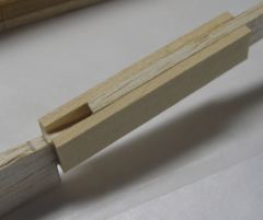 Propeller shaft tunnel finished - note faint pencil marks for bulkhead #4 just to the left of the doublers.
Attaching the Keel
Before attaching the keel, take small pieces (1/2 to 3/4" long) of balsa, the same thickness as the chine shelf, and attach to bulkhead #2, 3 and 4 right in the center. The purpose is to provide a temporary landing and support for the next step in fitting the lower triangular parts of the bulkheads.
When I built the prototype it took me a while to figure this out, so they may be missing in some of the pictures below.
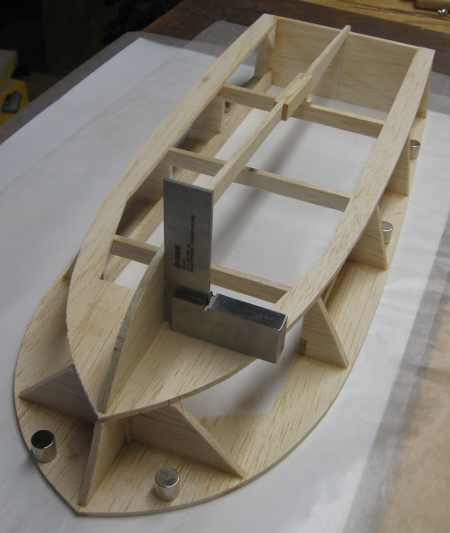 Dry-fitting the keel with a square.
Time to fit the keel. Just like when the deck was attached, keeping the keel perpendicular and centered is more important than locating front to back. The easiest and best way to locate the keel front to back is to sand the front-most part of the chine shelf flush to the angle of the stem piece. This way you'll have an edge that should correspond with the front-most edge on the keel.
As you can see on the picture below, I didn't do it this way, but it would have made things a little easier. Instead I eye-balled it in by looking at the profile and having the curved part of the keel tangent the angle of the stem. Either method works, but I highly recommend the former.
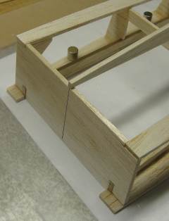 Transom and keel transition - note how the keel is lined up to the center line of the transom and flush at the rear.
Also look at where the keel meets the transom. By design, the keel should end at the stern face of the transom and be perfectly centered. Once all lines up, attach the keel with a few drops of CA while held perpendicular and in position.
The lower triangles that make up the rest of the bulkheads don't have templates, but are taken off the triangular shape created between the keel and chine shelf at each bulkhead location, or station as it is properly called.
First grab a piece of balsa a little wider than the height of the keel. At least one of the long edges need to be straight. Use a square and make a cut at a right angle to the straight edge.
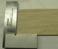 Cut a square angle at the end of a piece of balsa sheet.
Hold the square corner against the chine shelf and keel at station #3 with one hand. With the other hand, with a sharp pencil, mark the edge where the keel and chine shelf intersect (see picture below). All you need are two tick-marks.
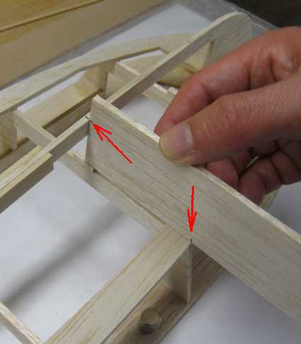 A square corner of a balsa sheet is held against the hull at each station and the edge of chine shelf and keel is marked on the balsa.
Lay the sheet down on your cutting surface and lay a straight-edge between the two tick marks and cut with a razor blade or X-acto knife. You can save a little time by using the first triangle at each station as a template for the opposite side.
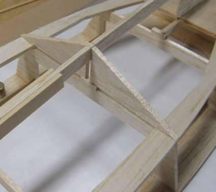 Lower bulkhead "triangles" in place at station #3.
I glue each pair in as I complete them. It breaks up the laborious task of trimming and cutting a little. Then use the same process for the other bulkheads. I like to work from the center and towards each end so it adds some well needed stability to the keel.
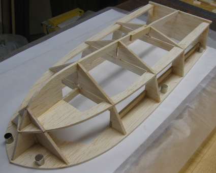 All the lower bulkheads are cut out and glued into place.
Now the hull frame is ready for sanding to smooth out the shape some and to give the skin more edge to hold onto. After that we'll start the planking process.
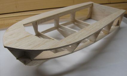 The RC boat hull flipped over ready for sanding and planking.


